RF Field Strength Meter (FSM) - Spectron.us
RF Field Strength Meter (FSM) - Spectron.us
RF Field Strength Meter (FSM) - Spectron.us

You also want an ePaper? Increase the reach of your titles
YUMPU automatically turns print PDFs into web optimized ePapers that Google loves.
<strong>RF</strong> <strong>Field</strong> <strong>Strength</strong> <strong>Meter</strong> (<strong>FSM</strong>)<br />
This is a description of a <strong>RF</strong> <strong>Field</strong> <strong>Strength</strong> <strong>Meter</strong> or <strong>RF</strong> “sniffer” if you prefer that name. The goal<br />
is to sensitively detect low level of high frequency <strong>RF</strong> fields. In this design the foc<strong>us</strong> is on the 2.5<br />
GHz band. However the described instrument is so sensitive that it will detect low level fields<br />
below 1000 MHz.<br />
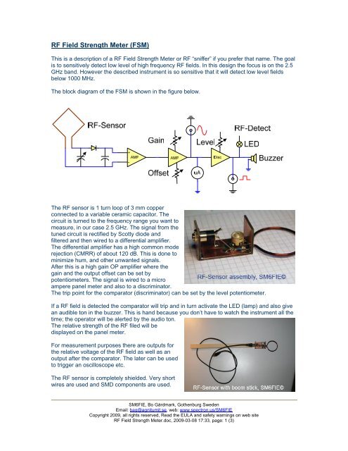
The block diagram of the <strong>FSM</strong> is shown in the figure below.<br />
The <strong>RF</strong> sensor is 1 turn loop of 3 mm copper<br />
connected to a variable ceramic capacitor. The<br />
circuit is turned to the frequency range you want to<br />
measure, in our case 2.5 GHz. The signal from the<br />
tuned circuit is rectified by Scotty diode and<br />
filtered and then wired to a differential amplifier.<br />
The differential amplifier has a high common mode<br />
rejection (CMRR) of about 120 dB. This is done to<br />
minimize hum, and other unwanted signals.<br />
After this is a high gain OP amplifier where the<br />
gain and the output offset can be set by<br />
potentiometers. The signal is wired to a micro<br />
ampere panel meter and also to a discriminator.<br />
The trip point for the comparator (discriminator) can be set by the level potentiometer.<br />
If a <strong>RF</strong> field is detected the comparator will trip and in turn activate the LED (lamp) and also give<br />
an audible ton in the buzzer. This is hand beca<strong>us</strong>e you don’t have to watch the instrument all the<br />
time; the operator will be alerted by the audio ton.<br />
The relative strength of the <strong>RF</strong> filed will be<br />
displayed on the panel meter.<br />
For measurement purposes there are outputs for<br />
the relative voltage of the <strong>RF</strong> field as well as an<br />
output after the comparator. The later can be <strong>us</strong>ed<br />
to trigger an oscilloscope etc.<br />
The <strong>RF</strong> sensor is completely shielded. Very short<br />
wires are <strong>us</strong>ed and SMD components are <strong>us</strong>ed.<br />
SM6FIE, Bo Gärdmark, Gothenburg Sweden<br />
Email: bag@agnitumit.se, web: www.spectron.<strong>us</strong>/SM6FIE<br />
Copyright 2009, all rights reserved, Read the EULA and safety warnings on web site<br />
<strong>RF</strong> <strong>Field</strong> <strong>Strength</strong> <strong>Meter</strong>.doc, 2009-03-08 17:33, page: 1 (3)
The <strong>RF</strong> sensor is connected to the measurement amplifier detector circuit via a two wire shielded<br />
cable. Some pictures of the <strong>RF</strong> sensor can be seen to the right. I did place a boom stick to make<br />
it easy to place and <strong>us</strong>e the sensor or <strong>RF</strong> pickup coil, if you want, to exact spots of my choice.<br />
The instrument is built into a small plastic box and<br />
is powered by a 9-volt battery. The intention is that<br />
the instrument shall easily be portable.<br />
The complete schematic for the instrument can be<br />
found via a link below in the reference section. The<br />
only comment I have is a note on the novel way to<br />
get the pl<strong>us</strong> and min<strong>us</strong> supply over a common<br />
ground for the operational amplifiers. Fancy!<br />
The circuit was built dead bug, New York style,<br />
follow this link for more information. A picture of the<br />
assembly can be found to the right. For more information about the “Dead Bug Manhattan Style”<br />
see the references below. For prototyping this technique is very good, fast, simple and good for<br />
up to above 100 MHz if you do it correctly. All is done on a circuit board that acts as a ground<br />
plane.<br />
During some test I found that the<br />
instrument easily could detect a<br />
DECT phone as well as my mobile<br />
phone. My WiFi wireless device<br />
gave a very strong indication. There<br />
was no problem to detect weaker<br />
signal like T<strong>RF</strong>-2.4G Transceiver<br />
from Spark Fun (based on the<br />
Nordic n<strong>RF</strong>2491 chip). This device<br />
has an output of 0 dBm +/- 3 dB or<br />
about one mille watt. In the picture<br />
“<strong>FSM</strong> in Action” you can clearly see<br />
how the <strong>FSM</strong> detects the 2.4 GHz<br />
signal from the T<strong>RF</strong>2.4G that is run<br />
in continues mode in this case.<br />
When doing software development for example for the T<strong>RF</strong>2.4G it has big values to actually see<br />
when the device radiates <strong>RF</strong> energy. When looking at the oscilloscope at the same time as you<br />
trace the program, row by row, I have also found that the audible ton from the <strong>FSM</strong>, when it<br />
detect <strong>RF</strong>, is very helpful.<br />
The electronic schematic, as said earlier, is included as a link at the reference section below.<br />
They schematics are more or less self-explanatory. I have also included, in PDF format the layout<br />
of the front panel for the instrument. It was done by Microsoft Visio. If someone want to have the<br />
original file please drop me a line and I will send it via email.<br />
Good <strong>RF</strong> hunt!<br />
SM6FIE, Bo Gärdmark<br />
You can also download this article in PDF format, see j<strong>us</strong>t click here.<br />
(www.spectron.<strong>us</strong>/SM6FIE/Electronics/<strong>FSM</strong>/<strong>RF</strong>_<strong>Field</strong><strong>Strength</strong><strong>Meter</strong>.pdf)<br />
SM6FIE, Bo Gärdmark, Gothenburg Sweden<br />
Email: bag@agnitumit.se, web: www.spectron.<strong>us</strong>/SM6FIE<br />
Copyright 2009, all rights reserved, Read the EULA and safety warnings on web site<br />
<strong>RF</strong> <strong>Field</strong> <strong>Strength</strong> <strong>Meter</strong>.doc, 2009-03-08 17:33, page: 2 (3)
References:<br />
Electronic schematics: www.spectron.<strong>us</strong>/SM6FIE/Electronics/<strong>FSM</strong>/<strong>FSM</strong>_Schematics.pdf<br />
Panel layout: www.spectron.<strong>us</strong>/SM6FIE/Electronics/<strong>FSM</strong>/ Panel_<strong>FSM</strong>_V2.pdf<br />
Prototyping: http://www.dartmouth.edu/~sullivan/prototyping.pdf<br />
Manhattan Building Techniques: http://www.k7qo.net/manart.pdf<br />
Manhattan Style: http://radio.thulesi<strong>us</strong>.se/div_mtrl/manhattan.htm<br />
SM6FIE, Bo Gärdmark, Gothenburg Sweden<br />
Email: bag@agnitumit.se, web: www.spectron.<strong>us</strong>/SM6FIE<br />
Copyright 2009, all rights reserved, Read the EULA and safety warnings on web site<br />
<strong>RF</strong> <strong>Field</strong> <strong>Strength</strong> <strong>Meter</strong>.doc, 2009-03-08 17:33, page: 3 (3)