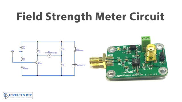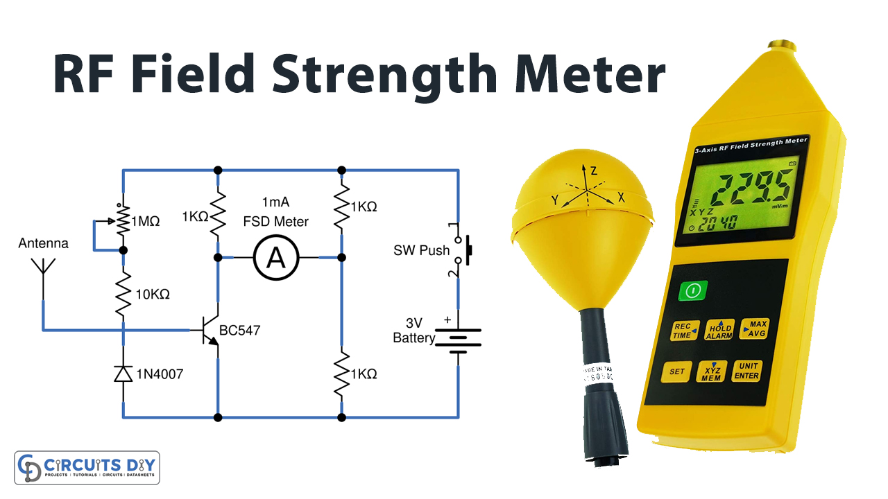
In this tutorial, we are going to make a “Field Strength Meter Circuit”.
A field strength meter is an electronic device that is used for detecting and measuring the RF radiation generated from any RF transmitter circuit. The field strength meter is a simple receiver. The RF signal is detected and fed to a micro ammeter. As transmitter circuits invariably use the tank circuit, oscillate at a specified resonating frequency to transmit the frequency in the air with optimum power. A field strength meter picks up this frequency radiation from the transmitter’s LC antenna network and displays its strength or power through the attached meter.
This circuit helps us to find the radio transmitting circuit working condition, which cannot be used to measure field strength accurately. If you need to measure field strength for critical applications then use a digital field strength meter.
Hardware Components
The following components are required to make Field Strength Meter Circuit
| S.no | Component | Value | Qty |
|---|---|---|---|
| 1. | Transistor | BC547 | 1 |
| 2. | Resistor | 10KΩ, 1KΩ | 1,1 |
| 3. | Variable Resistor | 1MΩ | 1 |
| 4. | FSD ammeter | 1mA | 1 |
| 5. | Diode | 1N4007 | 1 |
| 6. | Push-button switch | – | 1 |
| 7. | Antenna | – | 1 |
| 8. | Connecting Wires | – | – |
| 9. | Power Supply | 3V | 1 |
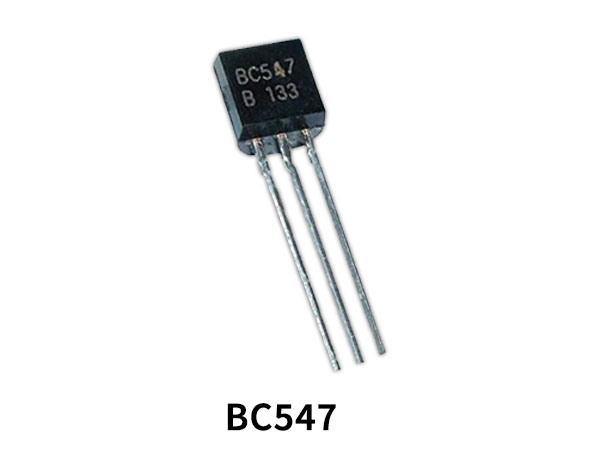
BC547 Pinout

For a detailed description of pinout, dimension features, and specifications download the datasheet of BC547
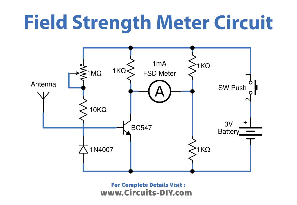
Field Strength Meter Circuit
Working Explanation
This field strength meter circuit uses a 1mA FSD ammeter DC, indicating the radio magnetic field strength between 0 to 1mA scale range. we can construct this circuit easily without complex steps. Here we use only one transistor and a few external components. Begin with bias resistors to BC547, connect variable resistor RV1 in series with R1, and connect diode D1 in reverse polarity to the base of the transistor. This diode D1 will eliminate the reverse polarity signal from the antenna.
Then place 1mA FSD ammeter DC between transistor collector and Voltage divider resistors R3 and R4, make sure to connect meter positive terminal to the voltage divider circuit. Now to power, the whole circuit you can use a CR2025 coin battery or AAA battery as we need 3V. In the end, a push-button switch is placed in the power supply path. We can measure the field strength by pressing this switch only.
Applications
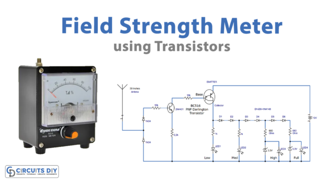
This circuit can be used to detect the magnetic field strength of radio signals and common radio transmitting signals through an antenna.
It is also used to adjust an antenna to get the best gain and to determine the transmitting range of radio controllers.